CAD Details
Here you will find PDFs of our CAD Details that illustrate how our system installs on different surfaces and in and around various architectural features. These are perfect for use in your project plans and specs.
Write a review
| Videos Gallery | 01/05/2024 |
|---|---|
|
|
4 days 10 hours 40 minutes |
|
|
8 |
CAD Detail of Classic-Line® FS105 1/2" Square Front-Load Low-Leg Profile system.
Slim-Line® 1/4 inch
View allCAD Detail of Slim-Line® FS005 1/4" Square Front-Load Profile system being installed on drywall above and below a chair rail and above a baseboard.
CAD Detail of Slim-Line® FS005 1/4" Square Front-Load Profile system being installed on drywall next to a ceiling or soffit.
CAD Detail of Slim-Line® FS005 1/4" Square Front-Load Profile system being installed on drywall in conjunction with wood or MDF blocking to cover an outside corner where two walls meet.
CAD Detail of Slim-Line® FS005 1/4" Square Front-Load Profile system being installed on drywall and above a baseboard with a horizontal intermediate joint joining two panels.
Classic-Line® 1/2 inch
View allCAD Detail of Classic-Line® FS100 1/2" Square Front-Load Profile system being installed on drywall next to door and window trim.
CAD Detail of Classic-Line® FS105 1/2" Square Front-Load Low-Leg Profile system being installed on drywall above a baseboard or countertop backsplash.
CAD Detail of Classic-Line® FS100 1/2" Square Front-Load Profile system being installed on drywall at an inside corner where one wall meets another.
CAD Detail of Classic-Line® FS100 1/2" Square Front-Load Profile system being installed on concrete.
Full-Line® 1 inch
View allTypical basement layout CAD Detail of Classic-Line® FS100 1/2" Square Front-Load Profile system being installed on drywall below a ceiling, above and below a chair rail and above a baseboard.
CAD Detail of Full-Line® FS150 1" Square Front-Load Profile system being installed on drywall above a baseboard or countertop backsplash.
CAD Detail of Classic-Line® FS100 1/2" Square Front-Load Profile system being installed on 1" shim material below a ceiling, above and above a baseboard with an intermediate joint.
Typical basement layout CAD Detail of Classic-Line® FS100 1/2" Square Front-Load Profile system being installed on drywall between a ceiling and baseboard with an intermediate joint.
Max-Line® 2 inch+
View allCAD Detail of Full-Line® FS150LF 1" Square Front-Load Profile system.
CAD Detail of Typical Wall Application using the Classic-Line® FS100 1/2" Square Front-Load Profile system.
CAD Detail of Classic-Line® FS105 1/2" Square Front-Load Low-Leg Profile system.
CAD Detail of Full-Line® FS150HF 1" Square Front-Load Profile system.
Deluxe-Line® 2 Inch
View all
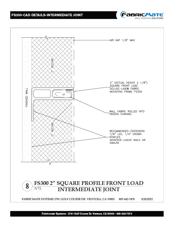
CAD Detail of Deluxe-Line® FS300 2" Square Front-Load Profile system.
CAD Detail of Deluxe-Line® FS300 2" Square Front-Load Profile system.
CAD Detail of Deluxe-Line® FS300 2" Square Front-Load Profile system.
Here you will find PDFs of our CAD Details that illustrate how our system installs on different surfaces and in and around various architectural features. These are perfect for use in your project plans and specs.